Ad Banner Placeholder
Cambridge IGCSE Physics · 0625
Chapter 4: Electricity and magnetism — Part 9
Topic 4.3.3 · Action and use of circuit components
Resistance and p.d. at constant current
For a constant current, the p.d. across a conductor increases as its resistance increases (because V = IR).
The potential divider
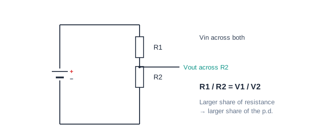
A potential divider is two (or more) resistors in series across a supply. The supply p.d. is shared in proportion to the resistances.
For two resistors: R1 / R2 = V1 / V2
A potential divider is made from 2.0 kΩ and 4.0 kΩ in series across 12 V. The output is taken across the 4.0 kΩ resistor. Calculate the output p.d.
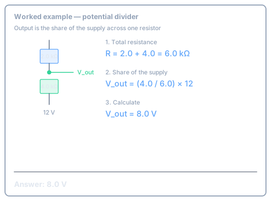
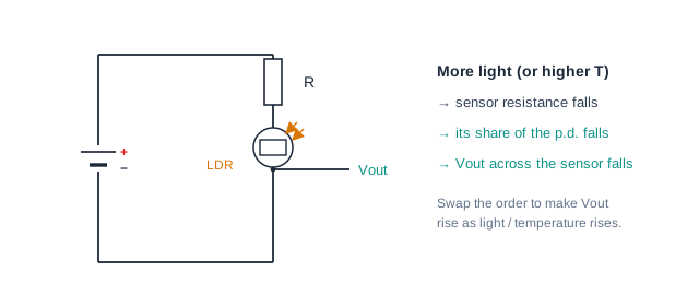
The output is the p.d. across one of the resistors. A variable resistor, LDR or NTC thermistor in the divider makes the output change with setting, light or temperature.
0/10
Ad Banner Placeholder